Musical DRSSTC
As an electrical engineer, I'm always intrigued my high voltage gadgets and am very much a "Mad Scientist". Unsurprisingly, my favorite inventor is none other than Nikola Tesla, with his well known Tesla Coil being one of my favorite gadgets.
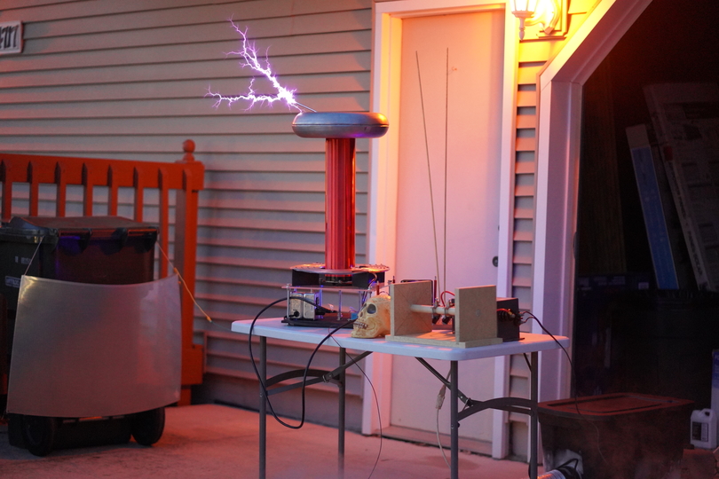
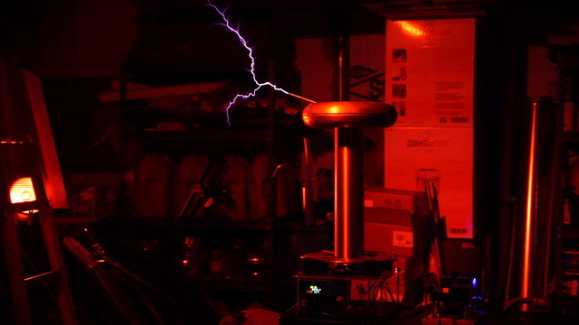
And since I'm also a musician, my favorite type of Tesla Coil is the Dual-Resonant Solid-State Tesla Coil (or DRSSTC) that is driven by a Music-based interrupter such that the music is heard as the artificial thunder for the artificial lightning being created.
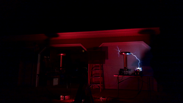
Since such Tesla Coils are very loud, every year I use Halloween as an excuse to drag my coils outside to make noise on a night that the neighbors aren't likely to complain. I call the annual event "Shock-or-Treat". The initial name came from the idea of setting up two live Tesla Coils and placing a bowl of candy in the middle between them. Would the kids get shocked or would they get a treat? OK, so I don't really do that with the candy bowl. But the name has stuck and has been an annual event now since 2018.
The first two years' events featured only a single coil. But by 2020, I added a second identical coil, playing them in stereo. However, the logistics of getting two coils running, coupled with my continual experimentation to achieve the best sound with the largest arcs simultaneously, while adding additional circuitry like TCDAQ or Tesla Coil Data Acquisition and Telematics, somewhat plagued the event in the years that followed. Though sometimes problems were just due to lack of time to get things tested and working in time, especially when the stupid mayors decided to move the Halloween Trick-or-Treat night from Monday the 31st to Saturday the 29th, in 2022, which robbed me of the weekend that I desperately needed to get things ready.
Currently, my coils use the traditional MIDI interrupter techniques to play music, which is a bit like playing sheet music, allowing the electronics to control the timing and duty cycle of each note. My present MIDI interrupter design allows for up to 34 simultaneous notes per coil. However, I'm actively working on what I consider to be "the holy-grail" for DRSSTC coils, which is Direct Audio Drive (DAD), where the coil can be driven from a sound track like an .mp3 file or even a microphone, but done in such a way as to preserve the sound quality of the MIDI drive. For that, I'm presently throwing nearly every bit of technology I can at the problem, combining DSP coprocessors and FPGAs, in addition to the main MCU of the interrupter. I've made great progress in that arena and nearly have a major milestone accomplished, if only I can keep the bridge transistors from blowing up!
-
Bench Testing DRSSTC Driver v5
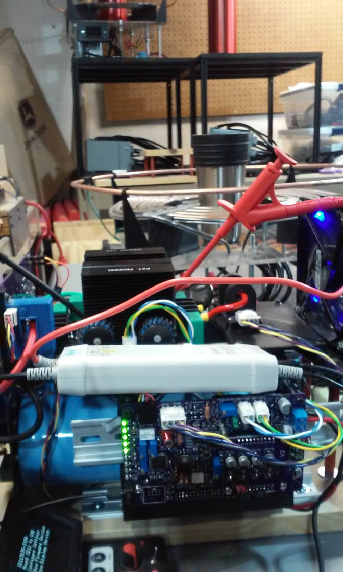
Picture of bench testing the latest v5 driver board for my Musical Tesla Coil. This driver uses CPLD-based logic and was developed for experimenting with H-bridge freewheeling. The box sitting on top of the circuit boards is part of the high-voltage differential probe used to isolate the bridge voltage measurements from the test instruments. The differential probes are visible in the background, connected across the bridge transistors. In the foreground, in the 3D printed case with the OLED display, is the MIDI interrupter control box used to remotely feed music and test signals to the driver via a fiber-optic link. It's called an "interrupter" because it interrupts what would otherwise be a continuous-wave oscillation of the Tesla Coil, in this case with music pulses created from MIDI data, such that the music is audible in the arc by the heating and cooling of the surrounding air.
-
Scope Showing BPS Test Pulse Ring-up
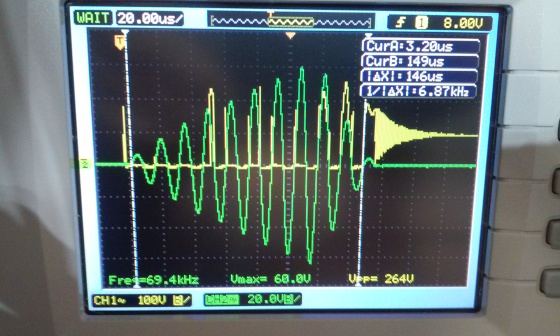
Bench testing scope shot of a BPS (bangs-per-second) pulse on the v5 driver.
-
Explaining the DRSSTC Circuit
Explaining the DRSSTC Bridge circuit to my coworker and neighbor, Leo Fan.
-
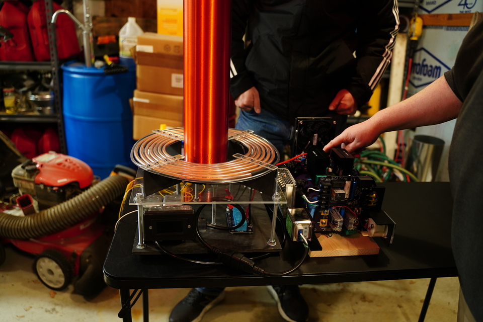
Garage Test Session
Test session running the coil in the garage prior to the 2019 Shock-or-Treat event. Click here to see the video from this test session.
-
Arc-Over Destroying the Electronics
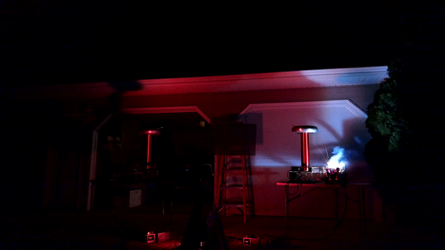
During the 2021 Shock-or-Treat event, one of the coils suffered an arc-over incident, which is where the lightning bolt strikes the electronics driving the coil rather than breaking out on the other side as desired. This led to adding a strike-ring and an isolation enclosure for the electronics for future events.
Circuits
All of my designs are open-source. Here's links to schematics of the latest versions the boards running my coils, along with links to OSHPark for PCB Fab.
There's basically two main configurations -- 1) with smaller TO-3P (similar to TO-247) footprint IGBT transistors -- specically the FGA60N65SMD and 2) with the larger IGBT bricks, specially the SMK200GB124D and SMK400GB125D or the CM600DU-24NFH, etc. My project began with the smaller transistors but my designs are gradually becoming more and more generic to merge the two into a universal mix. Some of the boards are specific to one configuration and other boards are the same for both (see notes below).
Small Transistor Configuration: |
Large Transistor Configuration: |
Notes:
|
FOLLOW OUR MISSIONS ON


© 2023 by Dewtronics/Donna Whisnant | All Rights Reserved